What is SAI-HUB DD?
SAI-HUB DD (DJI Dock) is an enterprise-grade drone automation software platform designed for on-premises, local-processing environments. All data processing and storage happen entirely on your Brain-Box hardware: ensuring data sovereignty, low-latency operations, and full functionality without an internet connection.
The platform enables operators to plan, schedule, and execute fully automated drone missions using DJI Dock 2 and Dock 3 docking stations. With six mission types, 19 AI detection algorithms running locally, and flexible three-tier connectivity, SAI-HUB DD delivers professional drone automation at any scale.
DD stands for DJI Dock. SAI-HUB DD is compatible with DJI Dock 2 and Dock 3 systems.

100% On-Premises
All data is processed and stored locally on your Brain-Box. No cloud dependency required for core operations.

AI-Powered Inspection
preloaded object detection algorithms run locally in real time: no external API or internet required.

Scheduled Automation
Schedule recurring missions for fully unattended routine inspections around the clock.

6 Mission Types
From simple linear patrols to AI-triggered patrol routes and fully custom per-waypoint missions.
Installation & Commissioning
Complete this section before using the SAI-HUB DD mission interface. The commissioning sequence is: install the DJI Dock according to DJI requirements, mount and cable the Brain-Box D, configure the dock to use the Brain-Box D as its third-party cloud service, then open SAI-HUB DD locally in a browser.
Choose Your DJI Dock
Select the dock model installed at your site. Only the relevant hardware mounting, cable routing, and DJI setup instructions will be shown.
DJI Dock 2 + Brain-Box D

Before mounting: installation checklist
| Category | Item | Quantity / Notes |
|---|---|---|
| Hardware | Brain-Box D | 1 |
| Hardware | Dock 2 custom mount | 1 |
| Fasteners | M2 screws | 4 |
| Fasteners | M6 bolts | 4 |
| Fasteners | M6 nuts | 4 |
| Fasteners | Washers | 4 |
| Connection | Ethernet connector | 1 |
| Tool | Phillips screwdriver | Required for bracket mounting and final fastening |
| Tool | 10 mm wrench | Required for final fastening |
Mount the Brain-Box D
- 1Remove the Dock 2 nameplate. Remove the four screws securing the DJI Dock 2 nameplate.
 Dock 2: Step 1: remove the nameplate
 - 2Install the custom bracket. Use the four supplied M2 screws and a Phillips screwdriver to secure the Dock 2 custom bracket.
 Dock 2: Step 2: secure the custom mounting bracket
 - 3Open the Brain-Box D lid. Rotate the four built-in lid screws from locked 1 to unlocked 0 to access the mounting holes.
- 4Insert the M6 bolts. Insert the four M6 bolts through the Brain-Box D mounting holes. Do not use the corner holes; those are reserved for the lid's built-in screws.
- 5Attach the Brain-Box D to the bracket. Align the Brain-Box D with the bracket, pass the M6 bolts through the bracket, and secure them with the washers and nuts. Start all four fasteners before fully tightening, then tighten securely using the Phillips screwdriver and 10 mm wrench.
 Dock 2: Step 5: align and fasten the Brain-Box D to the bracket
 - 6Close and lock the lid. Rotate the four built-in lid screws from unlocked 0 back to locked 1.
Connect Dock 2 Cables and Power
- 1Plug the Brain-Box D Ethernet connector into the dock LAN-IN port until a click is heard.
 Dock 2: Step 1: connect the Ethernet link to LAN-IN
 - 2Plug the Brain-Box D power connector into the AC-IN port until a click is heard.
 Dock 2: Step 2: connect Brain-Box D power to AC-IN
 - 3Plug the main power connector into a 110-240 VAC socket. The Brain-Box D powers on automatically. The DJI Dock can then be powered on according to the DJI Dock 2 manual.
Configure DJI Dock 2 for SAI-HUB DD
Complete the standard DJI Dock 2 setup using the latest DJI Installation and Setup Manual. During the DJI setup, apply the following SAI-HUB DD-specific settings:
- 1The SIM module in the dock/drone is optional and is not required for local SAI-HUB DD operation.
- 2On Network Configuration, an error may appear because the deployment is being used offline. This can be ignored for the local setup.
- 3On Cloud Service Configuration, do not connect the dock to FlightHub. Set Cloud Service to Third-Party Cloud Service.
- 4Set MQTT gateway address to mqtt://10.42.0.1:1883.
- 5Leave all fields marked Optional empty.
- 6Alternative landing-site configuration and Controller B are optional and are not required for the standard SAI-HUB DD installation.
DJI Dock 3 + Brain-Box D

Before mounting: installation checklist
| Category | Item | Quantity / Notes |
|---|---|---|
| Hardware | Brain-Box D | 1 |
| Hardware | Dock 3 custom mount | 1 |
| Fasteners | M4 screws | 4 |
| Fasteners | M6 bolts | 4 |
| Fasteners | M6 nuts | 4 |
| Fasteners | Washers | 4 |
| Connection | Ethernet connector | 1 |
| Tool | DJI-supplied screwdriver | Can be used to remove the four Dock 3 screws in Step 1 |
| Tool | Phillips screwdriver | Required for bracket mounting and final fastening |
| Tool | 10 mm wrench | Required for final fastening |
Mount the Brain-Box D
- 1Remove the four Dock 3 mounting screws. Remove the four indicated screws from the DJI Dock 3 and keep them in a safe place. The screwdriver supplied by DJI can be used.
 Dock 3: Step 1: remove the four mounting screws
 - 2Install the custom bracket. Use the four supplied M4 screws and a Phillips screwdriver to secure the Dock 3 custom bracket.
 Dock 3: Step 2: secure the custom mounting bracket
 - 3Open the Brain-Box D lid. Rotate the four built-in lid screws from locked 1 to unlocked 0 to access the mounting holes.
- 4Insert the M6 bolts. Insert the four M6 bolts through the Brain-Box D mounting holes. Do not use the corner holes; those are reserved for the lid's built-in screws.
- 5Attach the Brain-Box D to the bracket. Align the Brain-Box D with the bracket, pass the M6 bolts through the bracket, and secure them with the washers and nuts. Start all four fasteners before fully tightening, then tighten securely using the Phillips screwdriver and 10 mm wrench.
 Dock 3: Step 5: align and fasten the Brain-Box D to the bracket
 - 6Close and lock the lid. Rotate the four built-in lid screws from unlocked 0 back to locked 1.
Connect Dock 3 Cables and Power
Dock 3 cable routing: the Brain-Box D is installed on the opposite side of the dock ports, so route the cables underneath the Dock 3 to reach the connection points.
- 1Route the cable underneath Dock 3 and plug the Brain-Box D Ethernet connector into the dock LAN-IN port until a click is heard.
 Dock 3: Step 1: route and connect the Ethernet link to LAN-IN
 - 2Route and plug the Brain-Box D power connector into the AC-IN port until a click is heard.
 Dock 3: Step 2: route and connect Brain-Box D power to AC-IN
 - 3Plug the main power connector into a 110-240 VAC socket. The Brain-Box D powers on automatically. The DJI Dock can then be powered on according to the DJI Dock 3 manual.
Configure DJI Dock 3 for SAI-HUB DD
Complete the standard DJI Dock 3 setup using the latest DJI Installation and Setup Manual. During the DJI setup, apply the following SAI-HUB DD-specific settings:
- 1The SIM module in the dock/drone is optional and is not required for local SAI-HUB DD operation.
- 2On Deployment Mode, select Fixed-Mounted Deployment.
- 3On Network Configuration, an error may appear because the deployment is being used offline. This can be ignored for the local setup.
- 4On Cloud Service Configuration, do not connect the dock to FlightHub. Set Cloud Service to Third-Party Cloud Service.
- 5Set MQTT gateway address to mqtt://10.42.0.1:1883.
- 6Fill the other fields marked Required with Test. Leave all fields marked Optional empty.
- 7Entry/exit routes and the alternative landing-site configuration are optional and are not required for the standard SAI-HUB DD installation.
Optional Brain-Box D Network Connection
Core SAI-HUB DD operation can remain local. If the Brain-Box D also needs site-network or internet connectivity, the hardware manual supports either Ethernet or a Nano SIM connection.
Nano SIM
Unscrew the waterproof SIM connector cap, insert a Nano SIM in the correct orientation, then securely retighten the cap to preserve the waterproof seal.

Waterproof Ethernet
Use Cat 5e or Cat 6 cable with a 6-9 mm cable diameter so the connector can seal correctly.

- 1Disassemble the supplied waterproof Ethernet connector and loosen the tail nut.
- 2Feed the Ethernet cable through the connector and crimp it to the pass-through connector using the T568B wiring standard. Ensure the PVC jacket is fully inserted and no conductors are exposed.
- 3Use a network cable tester to verify contact and the T568B wiring sequence, then insert the pass-through connector into the outer housing until it clicks.
- 4Tighten the tail sleeve and then the tail nut. Open the Brain-Box D LAN port cover and connect the Ethernet connector until it clicks into place.
Final Step: Open SAI-HUB DD
- 1Connect the operator computer, tablet, or phone to the same local network as the Brain-Box D.
- 2Open any modern web browser and enter the local Brain-Box hostname. Replace xxx with the three-digit Brain-Box number printed for your unit.
brain-box-xxx.local- 3When the SAI-HUB DD login page appears, sign in using the initial credentials supplied by Spectro AI.
- 4Change the initial username/password in account settings before normal operation.
If SAI-HUB DD does not open: check the Brain-Box D green status LED. If it is off, re-check the cable and power connection steps. If it is on, the Brain-Box D has power; verify local network access and dock/software configuration, then contact Spectro AI if the interface is still unavailable.
Platform Overview
SAI-HUB DD is included with one of two hardware packages. Your software license is tied to your hardware configuration.
Brain-Box D + SAI-HUB DD
A standalone Brain-Box mountable directly onto the DJI Dock. Ideal for fixed, permanent installations.
DockWatch Trailer + SAI-HUB DD
Mobile trailer with the Brain-Box pre-installed, plus an integrated aviation receiver for air traffic monitoring.
Connectivity Levels
SAI-HUB DD is fundamentally an on-premises system: your data never has to leave your site. Three connectivity levels let you match the access model to your operational setup.
On-Premises: Local Network
The Brain-Box and operator device share the same local network: typically the Brain-Box's own Wi-Fi access point or a site LAN. No internet required. All processing, storage, and control is fully local. This is the default and recommended setup for maximum performance and data security.
On-Premises: Control Room via Network
The Brain-Box is connected to your organisation's wider network (LAN or VPN), allowing operators in a separate building or control room to access SAI-HUB DD via browser: without internet exposure. Data remains fully on-premises. Ideal for centralised monitoring of one or more docks from a permanent control room.
Remote: SAI-HUB Online
For operators who need visibility from any location, SAI-HUB Online provides a secure internet portal to check the live status of your docks from anywhere in the world. Data processing and storage still happen on-premises on the Brain-Box: SAI-HUB Online is a remote status window, not a data relay. Contact Spectro AI for configuration details.
All three levels can coexist simultaneously: the Brain-Box handles them in parallel without any performance impact on running missions.
System Architecture
The Brain-Box is the central processing unit. It runs SAI-HUB DD, stores all mission data locally, and communicates with the DJI Dock over the local network. The operator interface is accessed via web browser on any networked device.
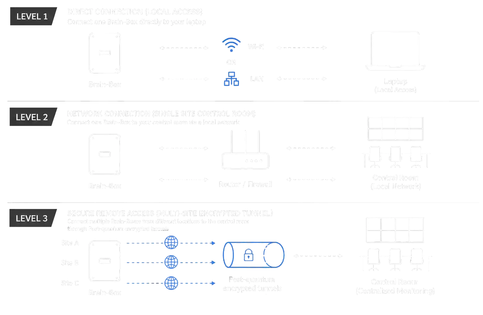
Brain-Box Architecture

First Login & Credential Setup
After the hardware installation and DJI Dock commissioning steps above are complete, access SAI-HUB DD locally using your Brain-Box D hostname. Spectro AI will provide your initial login credentials for first access.
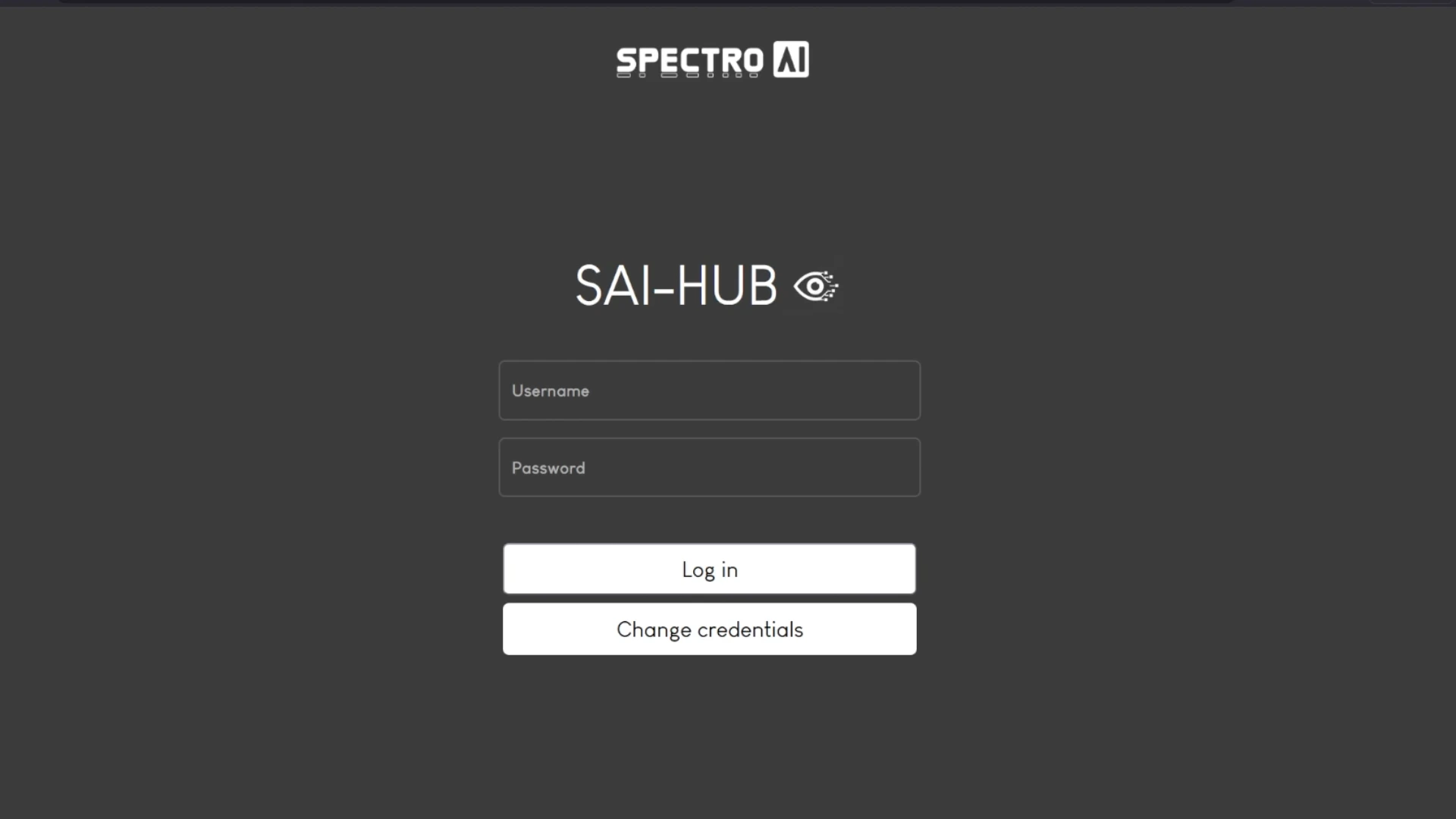
Change your credentials immediately after first login. Navigate to account settings and set a secure username and password before operating the system.
- 1Connect to the Brain-Box, the password is the same as the name.
- 2Open any browser and navigate to brain-box-xxx.local, replacing xxx with your Brain-Box number (for example, brain-box-064.local).
- 3Enter the credentials provided by Spectro AI and click Log In.
- 4Go to account settings and change your username and password immediately.
- 5You will arrive at the SAI-HUB DD home screen. Your system is ready to configure.
Missions
The missions dashboard is the first screen shown when you open SAI-HUB DD. Here is an overview of all your missions, with a live map, the dock location, and real-time telemetry.
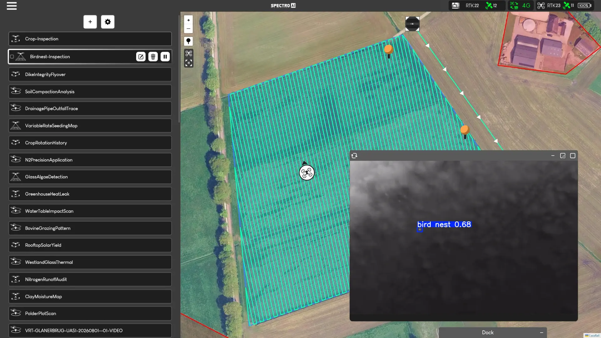
Map Controls (Top Left of Map)
| Icon | Function |
|---|---|
| + / − | Zoom in and out on the map |
 Annotations Annotations |
Open the annotation tool to place and manage markers on the map |
 Dock Location Dock Location |
Re-centre the map on the dock's current position |
 Drone Location Drone Location |
Re-centre the map on the drone's current position |
Map Icons
| Icon | Meaning |
|---|---|
 Drone Drone | Live drone position on the map |
 Dock Dock | Docking station location |
 Trailer Trailer Trailer Trailer | DockWatch Trailer location |
 Mission Start Mission Start | The first waypoint of the mission |
 Waypoint Waypoint | Mission waypoint marker |
 Annotation Annotation | Placed annotation marker on the map |
| ━ Turquoise coloured line | Planned flight route between waypoints |
| ▶ Solid white triangle | Flight direction indicators along the route |
 Resume Resume | Resume the mission from this waypoint |
Connection Status Bar
The connection status bar is always visible in the top right of every page. It shows live hardware and signal state across 11 indicators.
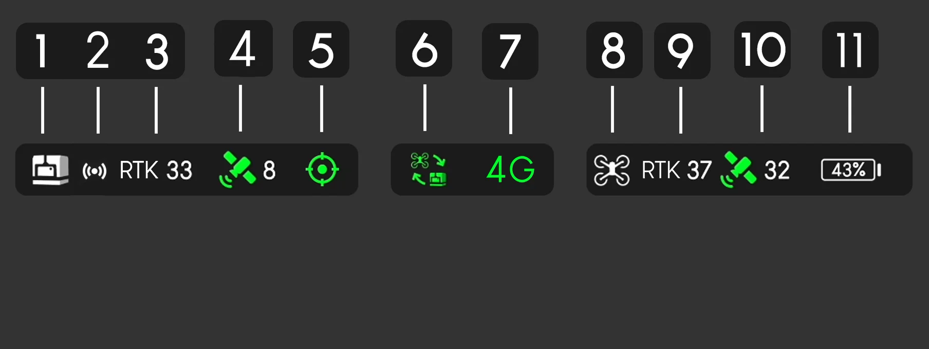

Dock
White = dock connected and online. Grey with a line through it = dock offline.

Livestream Active
Indicates an active video stream from the dock or trailer camera. Hover over this icon for a toggle to keep livestreams always visible on screen.

Dock RTK
Requires an active DJI RTK subscription. Without one this will always show grey/off.

Dock Signal
Green = strong GPS. Yellow = marginal. Red = poor signal.

Dock Positioning
Whether the dock's position is GPS-fixed. Green = fixed. Yellow = uncertain. Red = position unknown.
Software-Defined Radio
RF link quality between the drone and dock. Green / Yellow / Red = link quality.

4G / LTE
Mobile data signal for the dock's SIM card. Green / Yellow / Red = signal strength.

Drone
White = drone detected and connected. Grey = drone not detected.
Drone RTK
Requires an active DJI RTK subscription. Without one always shows grey/off.
Drone Signal
Green = strong GPS. Yellow = marginal. Red = poor signal.

Drone Battery
Live battery percentage of the drone. Colour changes from green to yellow to red as charge drops.
Air Traffic Toggle
Below the connection status bar in the top right, there is an icon to toggle air traffic visibility on the map. Depending on your hardware configuration this will read differently:
| Configuration | Air Traffic Source |
|---|---|
| Brain-Box D (no trailer) | AirSense: DJI's built-in ADS-B receiver, detects nearby aircraft transponders via the dock |
| DockWatch Trailer | Avionix: dedicated aviation receiver integrated into the trailer, providing enhanced air traffic detection range |
Mission Types
Click the + icon on the left side of the map to open the mission creation panel. Six mission templates are available.

Point of Interest
Orbits each waypoint in a configurable radius with the gimbal locked onto the target.

360° Waypoint
Full 360° rotation at each waypoint for complete panoramic capture.

Area Scan
Systematic grid pattern over a defined area for site-wide aerial mapping.

Linear Inspection
Straight-line path through all waypoints: ideal for pipelines, fences, and corridors.

Patrol Route
AI-triggered grid patrol for search and rescue. Operator can take over when a detection threshold is reached.

Custom
Configure each waypoint independently: freely mix orbits, 360° turns, grid sections, and straight segments.
Mission Parameters
Every mission shares a common set of parameters. Each mission type then adds its own specific options on top. The following parameters are present in all missions:
Patrol Route does not have a Capture option. Patrol Route is designed for search and rescue operations. It does not record video or images: it uses the AI detection pipeline to identify targets and alert the operator when the detection threshold is reached. Both RGB and thermal cameras can be searched simultaneously, though both streams cannot be viewed at the same time.
Mission Stats Panel (Top Right of Mission Creation Screen)
While planning a mission, the top right of the creation screen shows a summary of the calculated mission metrics based on your current waypoints and settings.
 Area Coverage
 Mission Length
 Estimated Time
Mission Length
Estimated Time
Estimated Time
Mission Length
Estimated Time
Click a mission type below to expand its unique parameters.
Capture Modes
The capture mode selector supports AI Video, Raw Video, Raw Images, or Disabled. The examples below show how the different zoom and camera behaviours appear in the interface.
Point of Interest
| Parameter | Description | Range / Options |
|---|---|---|
| Circle Radius | Orbit radius around each point of interest. | 5 m – 500 m |
| Flight Speed | Travel speed along the orbit path. | 1 – 15 m/s |
| Lens | Visible or infrared (IR). IR disables zoom selection. | Visible / IR |
| Zoom Level | Visible only. Multi-select: the orbit repeats once per selected zoom level. | 1× – 56× (multi) |
Gimbal Pitch: Not selectable: auto-locks onto the point of interest as the drone orbits.
360° Waypoint
| Parameter | Description | Range / Options |
|---|---|---|
| Gimbal Pitch | Camera angle during the 360° rotation. | −90° to +35° |
| Lens | Visible or infrared (IR). IR disables zoom selection. | Visible / IR |
| Zoom Level | Visible only. Multi-select: the full 360° rotation repeats once per selected zoom level. | 1× – 56× (multi) |
Area Scan
| Parameter | Description | Range / Options |
|---|---|---|
| Site Overlap Rate | Overlap percentage between adjacent grid passes. | 20% – 90% |
| GSD | Ground Sampling Distance: shows the exact pixel-to-centimetre ratio based on the selected zoom level, ensuring you achieve the spatial accuracy your data collection requires. | Variable (cm/px) |
| Lens | Visible or infrared (IR). IR disables zoom selection. | Visible / IR |
| Zoom Level | Visible only. Single select: one grid pass at the chosen zoom. | 1× – 56× (single) |
| Speed | Flight speed during the grid scan. | 1 – 15 m/s |
| Course Angle | Orientation of the grid lines relative to north. | 0° – 360° |
Gimbal Pitch: Not selectable: always nadir (straight down) to ensure consistent ground coverage across the grid.
Linear Inspection
| Parameter | Description | Range / Options |
|---|---|---|
| Speed | Flight speed along the linear route. | 1 – 15 m/s |
| Gimbal Pitch | Camera angle during the linear flight. | −90° to +25° |
| Lens | Visible or infrared (IR). IR disables zoom selection. | Visible / IR |
| Zoom Level | Visible only. Single select: one pass at the chosen zoom. | 1× – 56× (single) |
Patrol Route
| Parameter | Description | Range / Options |
|---|---|---|
| Lens | Visible or infrared (IR). IR disables zoom selection. Both RGB and thermal can be searched simultaneously, though only one stream is viewable at a time. | Visible / IR |
| Zoom Level | Visible only. Single select: one patrol pass at the chosen zoom. | 1× – 56× (single) |
| Gimbal Pitch | Camera angle during the patrol grid. | −90° to −30° |
| Speed | Flight speed across the patrol area. | 1 – 15 m/s |
| Side Overlap Rate | Overlap percentage between adjacent patrol passes. | 20% – 90% |
| Course Angle | Orientation of patrol grid lines relative to north. | 0° – 360° |
| Detection Threshold | Number of detections before an alert pop-up appears, offering the operator manual takeover or continuation of the mission. | Configurable count |
| Temperature Threshold | Temperature value that, when exceeded by a thermal detection, triggers an alert. | Configurable (°C) |
No Capture option. Patrol Route is designed for search and rescue operations and does not record video or images. The AI pipeline runs in real time and flags detections without saving media.
Custom
Custom missions let you configure actions separately for every waypoint. Click the map to place a waypoint. As soon as it is placed, a menu appears where you can select and configure the actions the drone should perform at that location.

Waypoint actions




Use the panel on the left to review the actions assigned to each waypoint and the distance between consecutive waypoints.

Gimbal Pitch Reference
| Mission Type | Gimbal Pitch Range |
|---|---|
| Point of Interest | Not selectable: auto-locks on the target |
| 360° Waypoint | −90° to +35° |
| Area Scan | Not selectable: always nadir (straight down) |
| Linear Inspection | −90° to +25° |
| Patrol Route | −90° to −30° |
| Custom | Per-waypoint: inherits the range of the assigned action type |
Zoom Level Reference
| Mission Type | Zoom Behaviour | Range |
|---|---|---|
| Point of Interest | Multi-select: orbit repeats once per zoom level | 1× – 56× |
| 360° Waypoint | Multi-select: rotation repeats once per zoom level | 1× – 56× |
| Area Scan | Single select: one grid pass at chosen zoom | 1× – 56× |
| Linear Inspection | Single select: one pass at chosen zoom | 1× – 56× |
| Patrol Route | Single select: one patrol at chosen zoom | 1× – 56× |
| Infrared (IR) lens disables zoom selection on all mission types. | ||
AI Video is a core differentiator of SAI-HUB DD. Video is processed through the Brain-Box AI pipeline in real time during the mission: detections are annotated and stored with metadata for immediate review, all locally without any cloud upload.
Pre-Flight Checklist
The Checklist module lets you define mandatory checks that must be confirmed before any mission launch. Checklists are fully customisable to match your operational procedures or regulatory requirements.
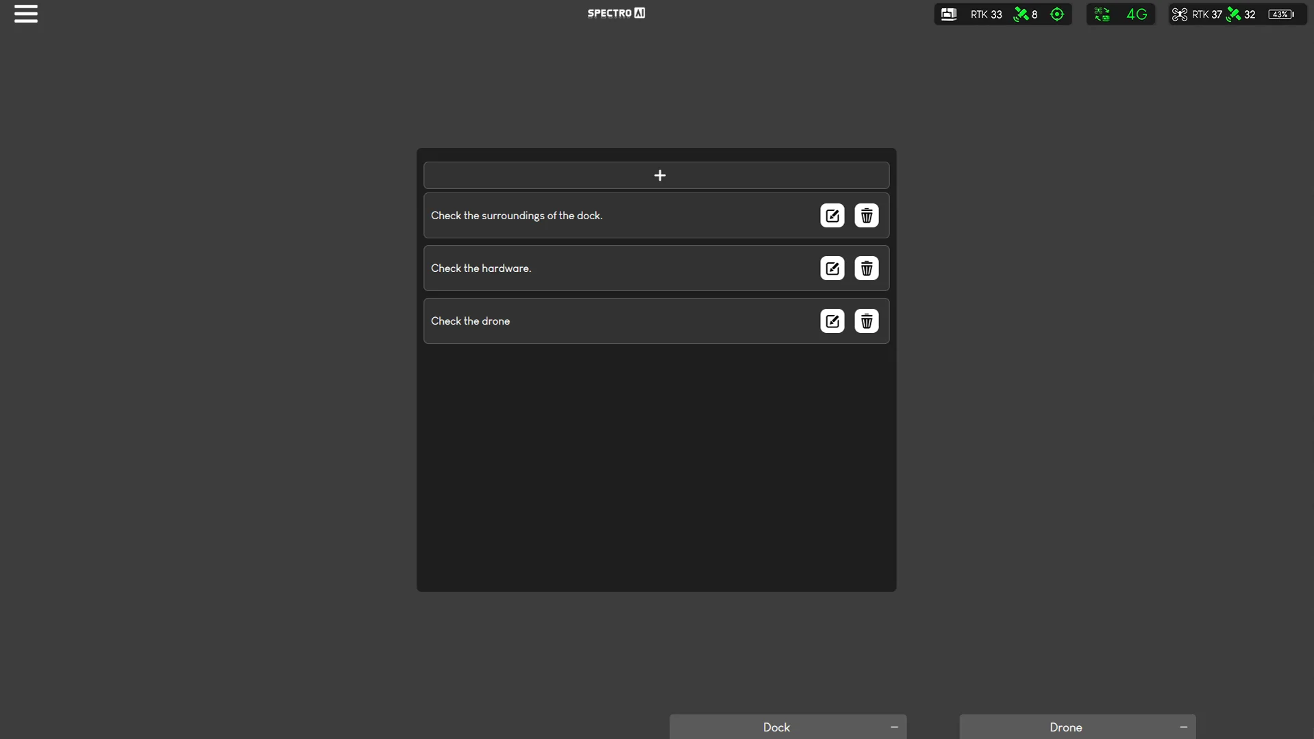
- →Navigate to Checklist in the left menu.
- →Add, edit, or remove checklist items from the management panel.
- →When enabled, all items must be confirmed before a mission can be launched.
Geofencing
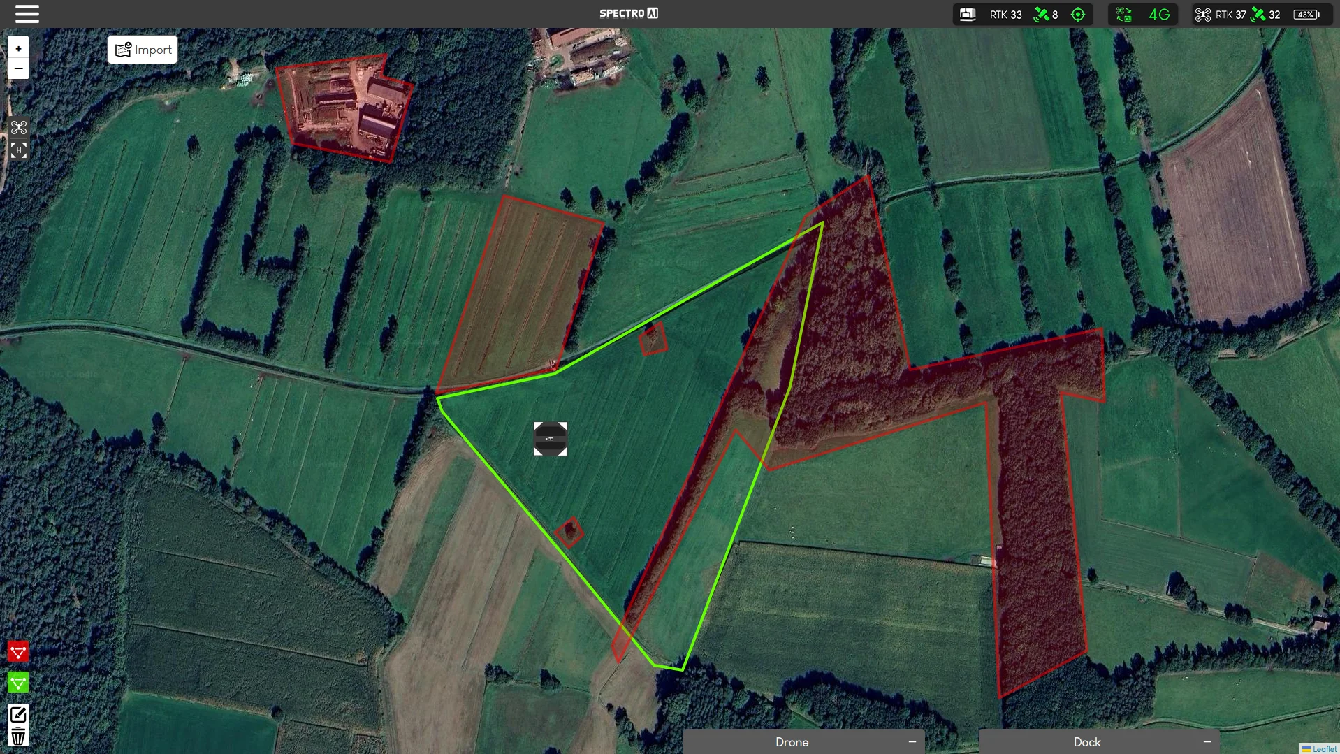
Define spatial boundaries for drone operations by drawing them on the map or importing existing geofences in KML or GeoJSON format. Two zone types are supported:
A Permitted Flight Zone is required before the drone can fly. Set up and save this boundary before planning or launching a mission.

Permitted Flight Zone
Defines the area in which the drone is allowed to operate. This zone is mandatory, and missions cannot be planned outside its boundary.
No-Fly Zone
Restricted areas the drone must never enter. Mission plans intersecting these zones are rejected before launch.
Virtual Cockpit
After you start any mission, SAI-HUB DD automatically opens the Virtual Cockpit. From here, you can observe the autonomous mission in real time or pause it and take over manual control whenever required.

Top Bar
- AIAI DetectionsTurns AI detections on or off for the live drone feed.
- DMDiscreet ModeTurns off the drone's lights for less visible operation.
- NMNight ModeLowers the camera frame rate so that more light can enter the sensor in dark conditions.
Main Buttons
 XGo to Safety HeightRaises the drone to the configured safety height before horizontal movement.
 HReturn to HomeCommands the drone to return to the dock and land.
 PPause MissionPauses the autonomous mission so the operator can observe or take over manually.
 OObstacle AvoidanceTurns the drone's obstacle-avoidance system on or off.
Telemetry Readouts
| Readout | Description |
|---|---|
 Wind Speed Wind Speed |
Live wind speed and direction from the drone's onboard sensors, shown with a compass indicator. |
 Dock Rain Sensor Dock Rain Sensor |
Current rain detection state at the dock location. |
| Gimbal Pitch | Current camera angle: adjustable in real time during manual flight. |
| Speed Level | Horizontal and vertical movement speed setting. |
 Altitude (ASL) Altitude (ASL) | Current altitude above sea level. |
| Dock Wind Speed | Wind speed reading at the dock location from the dock's sensors. |
Camera Pointing Controls
Right-click on the map to command the drone to rotate and point its camera towards that location. A contextual popup will appear at the clicked position.
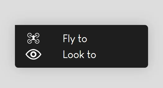
Double-click on the drone camera stream to lock the camera onto that position in the live video feed.
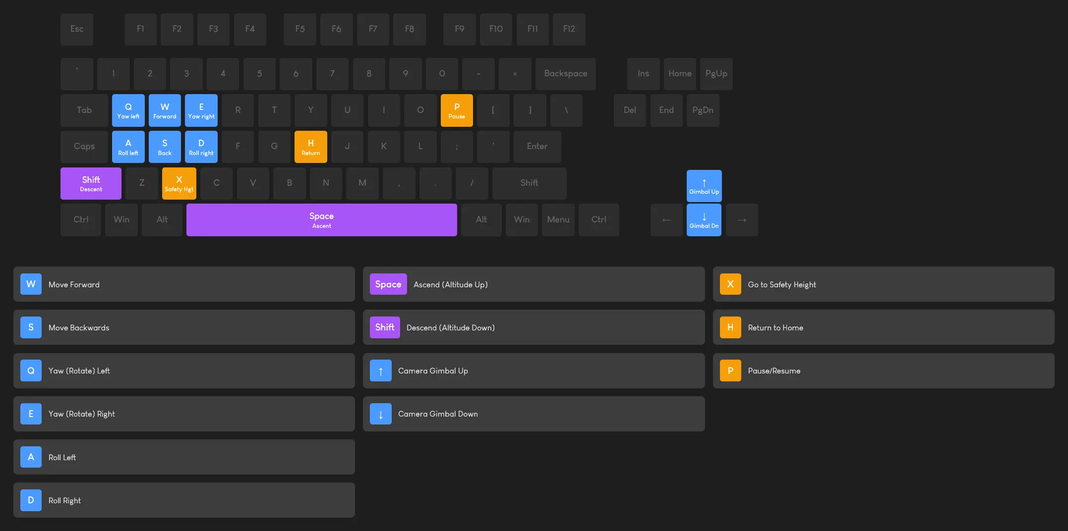
Keyboard Controls
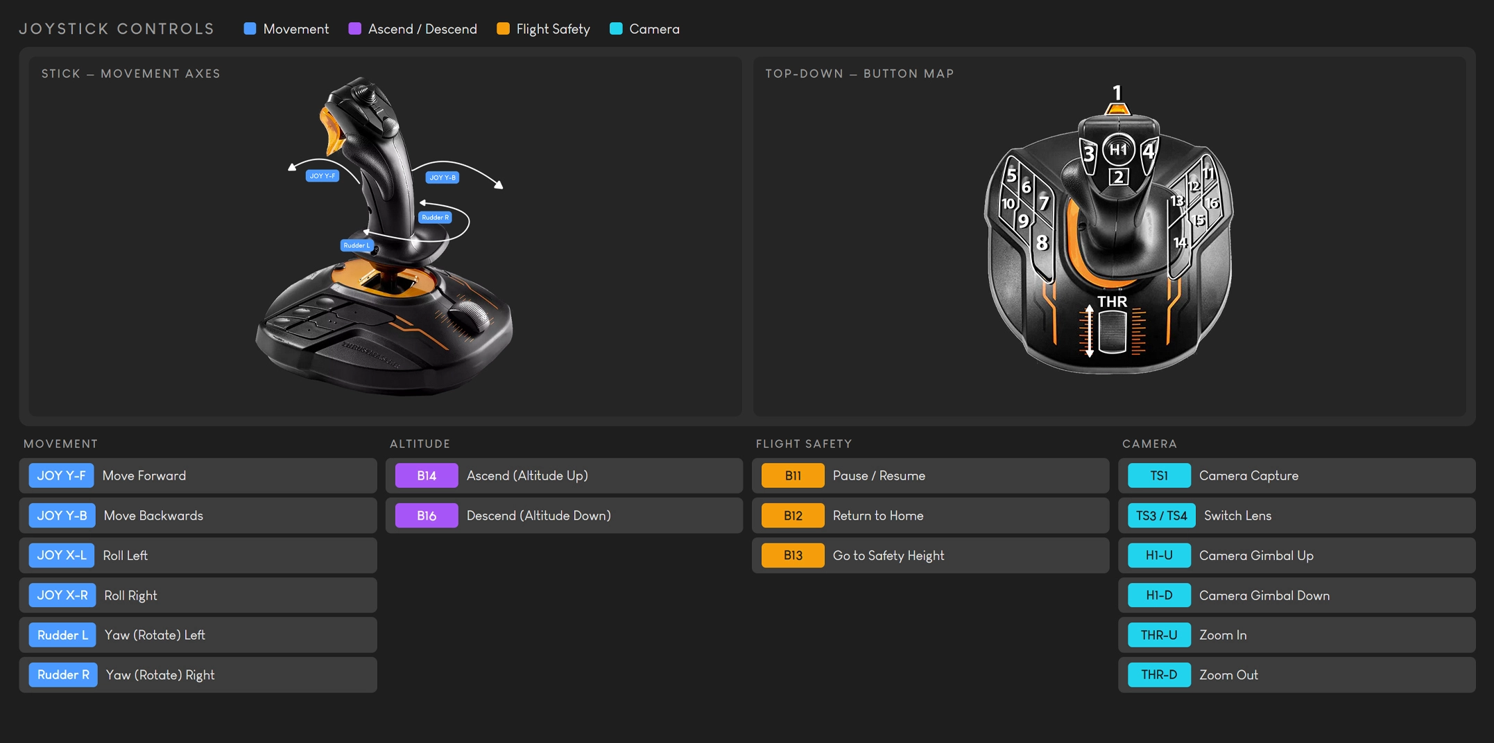
Joystick Controls
Live Streams
Live stream windows can be kept visible at all times while using the software: not only during missions. You can keep them open while navigating to any page, planning missions, or reviewing logs.

Available Streams by Configuration
| Configuration | Available Streams |
|---|---|
| Brain-Box D (no trailer) |
Dock weather station camera + Drone camera |
| DockWatch Trailer | Drone camera + Outside trailer camera + Inside trailer camera. The two trailer cameras can be toggled between each other. All streams can be displayed simultaneously. |
Stream Window Controls
Each stream window uses the following status and control icons:
 No StreamNo livestream is currently available.
 ReloadReloads the livestream if it becomes stuck or suddenly unavailable.
 Picture in PictureShrinks the stream into a small floating window.
 MinimizeMinimizes the drone stream and attaches it to the bottom-right corner of the screen.
 FullscreenOpens the stream in full-screen mode.
To keep stream windows permanently visible across all pages, hover over indicator 2 (Livestream Active) in the connection status bar and use the toggle to enable Always keep livestreams on screen.
Preloaded AI Algorithms
The Brain-Box includes preloaded computer vision algorithms that run entirely on-site, without a cloud service or external API. During a mission, the selected algorithm analyses the live camera feed, identifies matching objects, draws detections on the feed, and records useful metadata for later review.
For the full catalogue of available algorithms, target object classes, and recommended confidence thresholds, see the algorithm reference page: spectroai.ai/algorithms
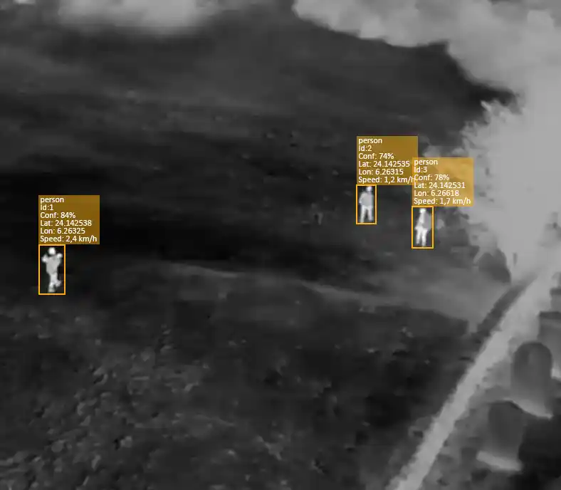
In mission setup, set Capture to AI Video, choose the algorithm and target object class(es), then set a confidence threshold. The Brain-Box processes the video feed in real time as the drone flies: detections are annotated and stored with metadata for immediate review.
Detection Data
Each detection stores the following parameters:
- IDA unique identifier for the detected object.
- Confidence %The algorithm's confidence score for the detection.
- LatitudeThe recorded latitude of the detection.
- LongitudeThe recorded longitude of the detection.
- SpeedThe detected object's speed, when applicable.
AI detection is assistive, not infallible. False positives and missed detections can occur depending on lighting, weather, camera angle, target visibility, environment, and model limitations. Use AI to support operations and prioritise review, with manual verification as the final decision step.
Gallery
The Gallery stores all imagery and video captured during missions on the Brain-Box internal storage. When you first open the Gallery, you are presented with a timeline view showing all recently captured media organised by period: today, this month, last month, and so on. This gives you quick access to the latest media without needing to navigate into a specific project.
To view media for a specific mission, click on a project in the left-hand panel. The gallery will filter to show only the media captured during that mission.
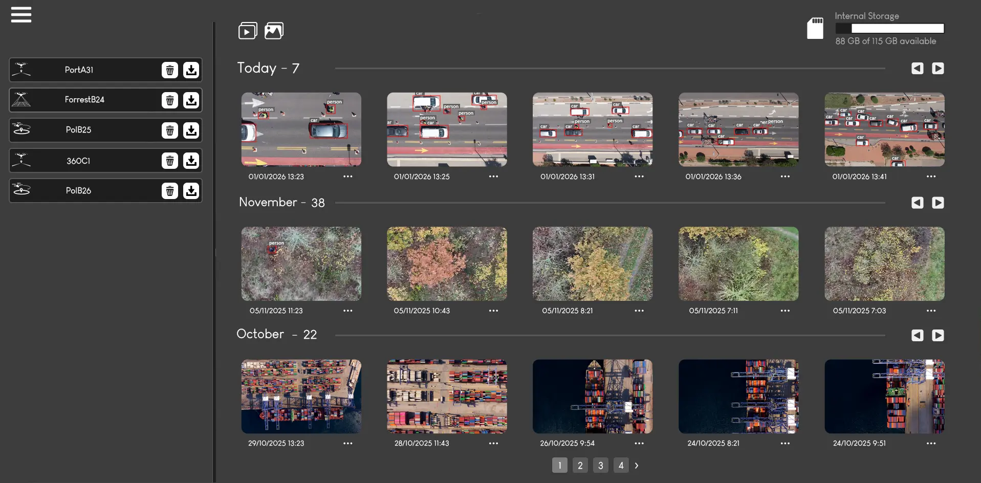
Filter by Media Type
Use the icons in the top left of the gallery to filter the view by media type:
 View Videos only
 View Images only
Downloading Media
Media can be downloaded in two ways:
 Download all: select a project and download all media within it as a single archive.
- Download individual: click any image or video to open it and download that single file.
File Attributes
| Attribute | Description |
|---|---|
| Date | Timestamp of when the media was captured |
| Type | Image (JPEG / RAW) or Video (MP4) |
| Size | File size on Brain-Box internal storage |
| Mission / Project | The mission during which the file was captured |
Flight Logs
Every completed mission generates a detailed flight log: including all parameters used, sensor readings, and a GPS-accurate route replay plotted from actual flight coordinates rather than the pre-planned estimate.
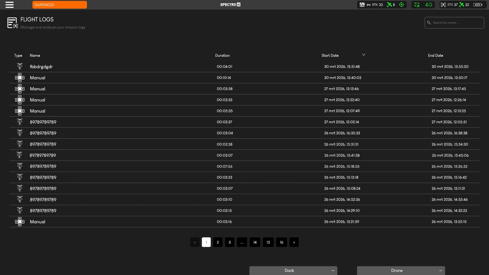
Clicking a specific mission opens its detailed replay view, showing the exact GPS route flown on the map together with the final mission outcome. The result clearly indicates whether the mission completed successfully or aborted, and whether that abort was triggered manually or automatically.
GPS Route Replay
View the exact path flown using real GPS coordinates: more accurate than any pre-planned estimate.
Flight Parameters
Review height, speed, duration, and all mission settings that were active during the flight.
Offline Maps
Upload offline map tiles and vector layers to the Brain-Box for map functionality without an internet connection. This is especially useful at remote or network-restricted sites, and vector layers can add operational boundaries or other reference information to the map.

Offline raster maps can be uploaded as GeoTIFF files of up to 1 GB per file. High-resolution tiles and additional vector layers are supported for precision operations.
GeoTIFF Import
GeoTIFF files can be imported as offline basemap layers or as geofence zone boundaries: eliminating manual drawing for complex or pre-defined operational areas.
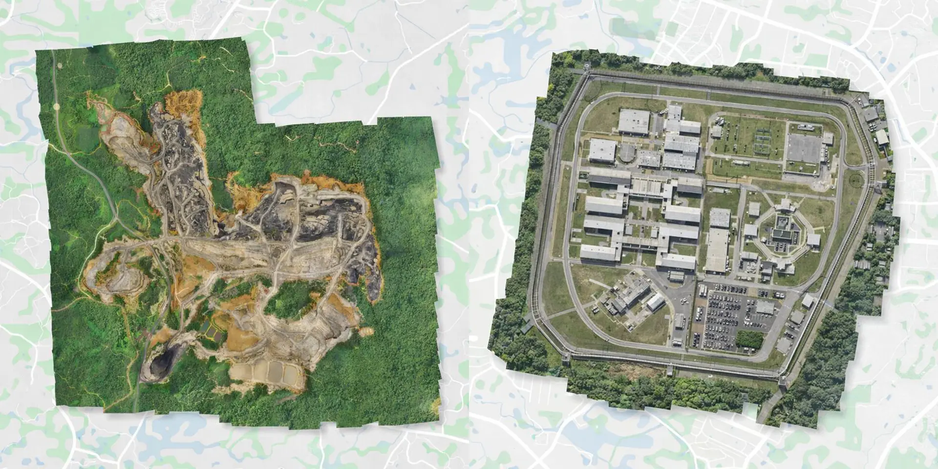
- 1Navigate to Maps in the left menu.
- 2Click Import GeoTIFF and select your file (max 1 GB).
- 3The map updates with the imported layer. Toggle it on or off as needed.
Annotation Markers
The annotation tool: accessed via the icon on the map: lets you place persistent markers and notes on any map location.
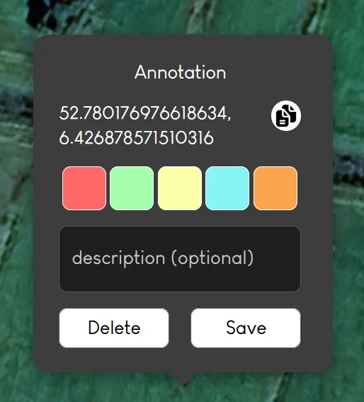
Annotations persist between sessions and are visible across all views of the map. Importantly, annotation markers are also visible in SAI-HUB Online: allowing remote users monitoring via the Level 3 portal to see the same markers placed by operators on-site.
Brain-Box
The Brain-Box page brings the appliance's firmware, power, network, and storage controls together in one place.
Brain-Box Page Overview

- Update Brain-Box FirmwareCheck for and install an available Brain-Box firmware update. Keep the Brain-Box powered and connected until the update finishes.
- Restart Brain-BoxSafely restart the Brain-Box from SAI-HUB DD. Active access is interrupted while the system restarts.
- Connect Brain-Box to Wi-FiSelect an available wireless network and enter its credentials to give the Brain-Box access through Wi-Fi.
- Connect External StorageConnect and manage external storage for additional media and mission-data capacity.
- External LANEnable the wired external network interface so devices on the site LAN can reach the Brain-Box. This option is not available for the DockWatch Trailer.
External LAN and Dock IP Configuration
Required after enabling External LAN: configure the DJI Dock to use the different Brain-Box IP address shown for External LAN. The dock will not reconnect to SAI-HUB DD if it remains configured with the original local Brain-Box address. Copy the External LAN IP shown in SAI-HUB DD, enter it in the dock's SAI-HUB DD / third-party cloud connection settings, save the change, and verify that the dock reconnects.
- 1Enable External LAN on the Brain-Box page and connect the external LAN cable.
- 2Note the External LAN Brain-Box IP address displayed by SAI-HUB DD.
- 3Open the DJI Dock configuration and replace the existing Brain-Box address with the External LAN IP address.
- 4Save the dock configuration and confirm in SAI-HUB DD that the dock connection is online again.
DockWatch Trailer: External LAN is not available for this configuration.
Dock
The Dock page shows all available DJI Dock and drone telemetry, hardware states, and operational controls.

Live Telemetry and Status
- Internal and external temperature
- Rainfall, humidity, and wind speed
- Air-conditioning and dock-cover state
- Drone and dock status
Dock Controls
- Calibrate RTKStarts RTK calibration for accurate positioning.
- Debug ModeTurns debug mode on or off for diagnostics.
- Silent ModeTurns silent operating mode on or off.
- Drone PowerTurns the drone on or off from the Dock page.
SAI-HUB Online
SAI-HUB Online is the remote status portal provided by Spectro AI. It lets you view the live status of your dock systems from any location in the world: no VPN or site network access required.
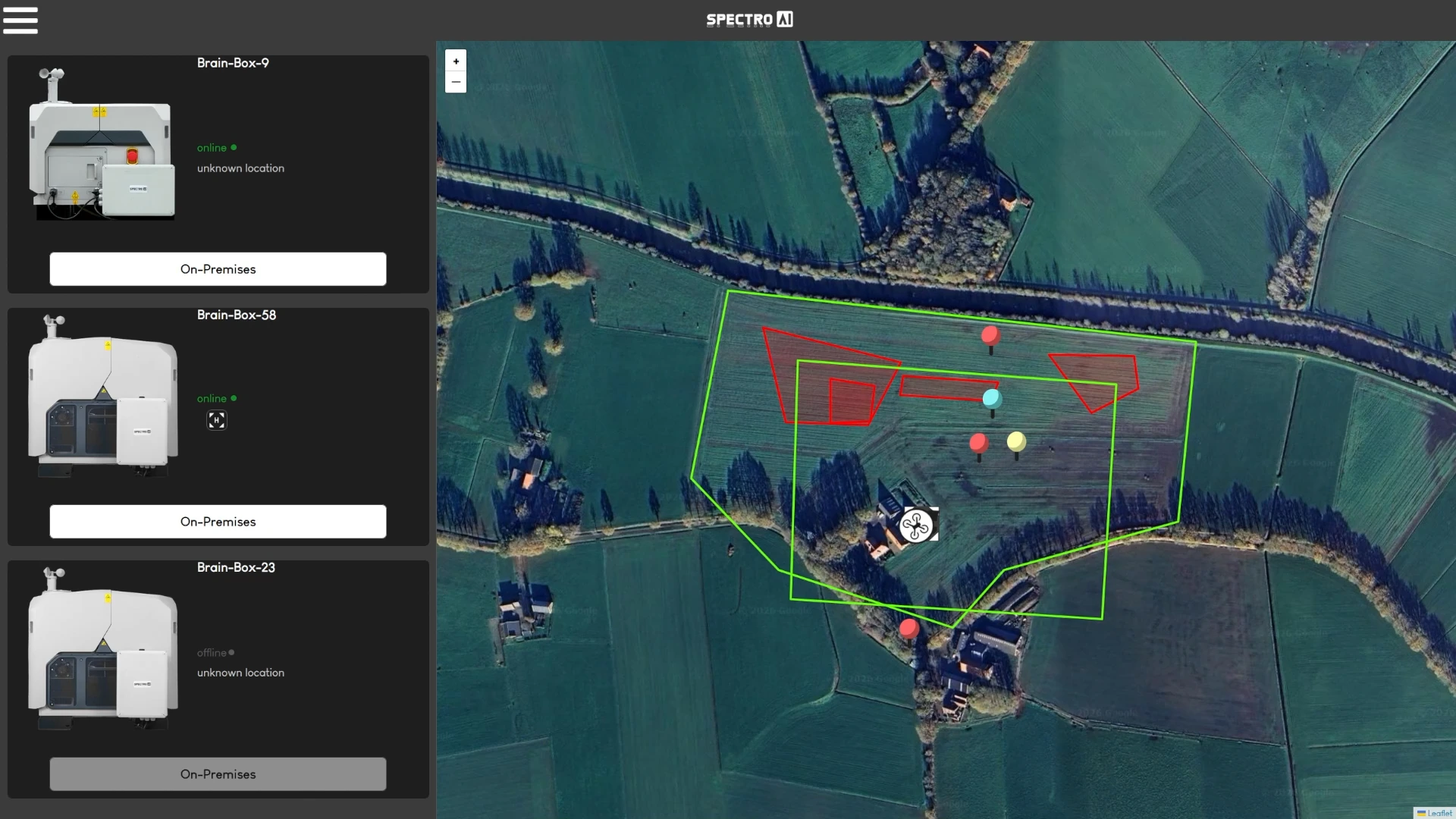
SAI-HUB Online is a status monitoring portal only. All data processing and storage remain on-premises on the Brain-Box: no mission data is uploaded to or stored in the cloud. Annotation markers placed on-site are visible here.
This is Level 3 connectivity in the three-tier access model. Useful for remote managers or fleet supervisors who need visibility without a direct network connection to the site. See Connectivity Levels for the full breakdown.
DockWatch Trailer Trailer Only
If you have purchased the DockWatch Trailer, the Trailer page provides access to trailer-specific cameras, sensors, and climate controls.
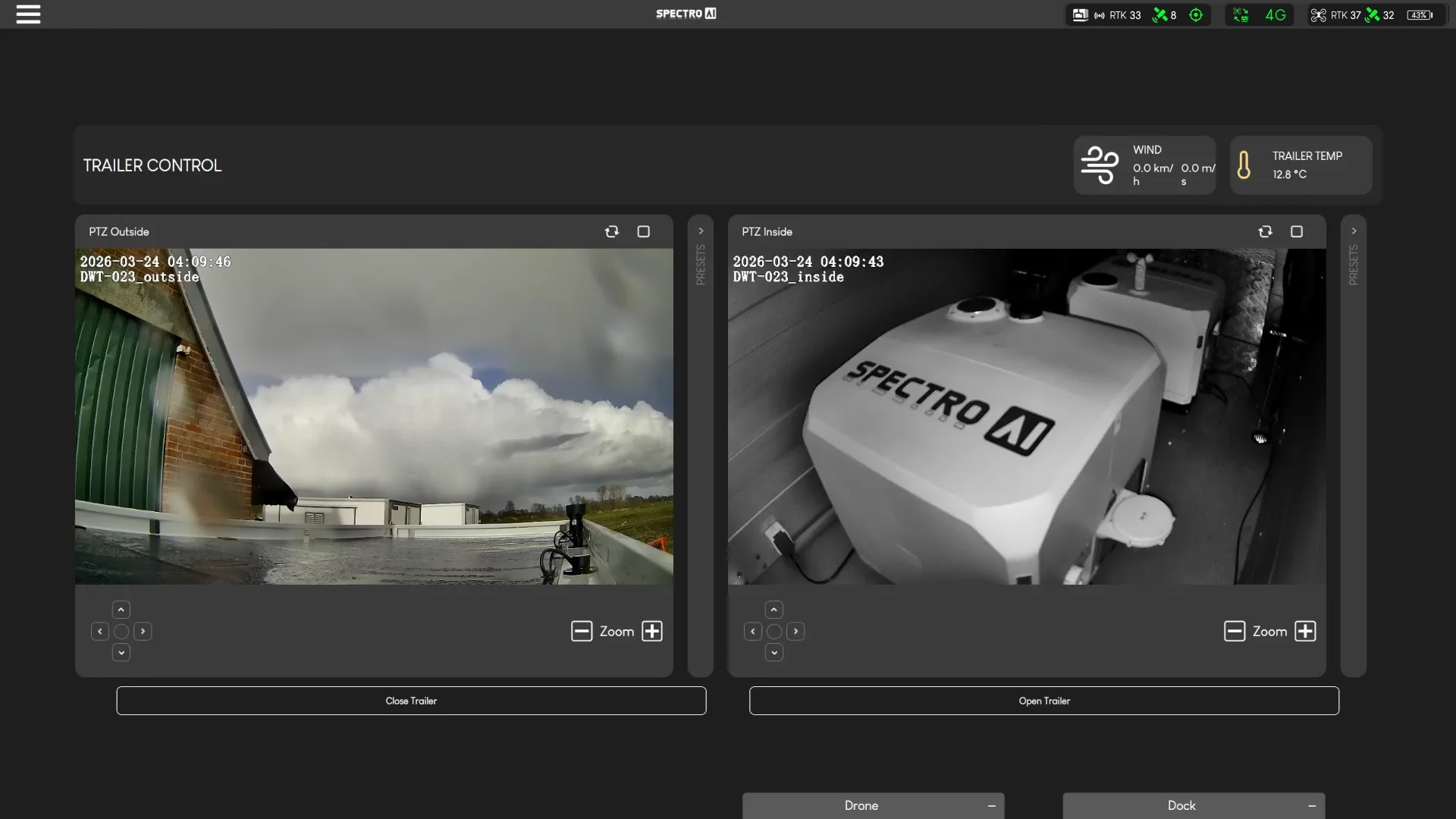
| Feature | Description |
|---|---|
| Trailer Camera Feeds | View both the outside and inside trailer cameras simultaneously. Switch between the two camera views as needed. |
| Viewing Angle Control | Adjust the pan and tilt of each trailer camera remotely from the interface. |
| Camera Presets | Save preset viewing positions for each camera: useful for quickly returning to key monitoring angles. |
| Air Conditioning | Set and adjust the target temperature for the trailer's internal climate control system. |
| Trailer Sensors | Monitor internal trailer temperature, wind conditions, and other environmental data. |
Air Traffic Monitoring
Both hardware configurations include air traffic awareness, though the source and range differ:
| Configuration | Source | Notes |
|---|---|---|
| Brain-Box D | AirSense (DJI ADS-B) | Built into the DJI Dock: detects aircraft transponders in the vicinity. |
| DockWatch Trailer | Avionix receiver | Dedicated aviation receiver with enhanced detection range integrated into the trailer. |
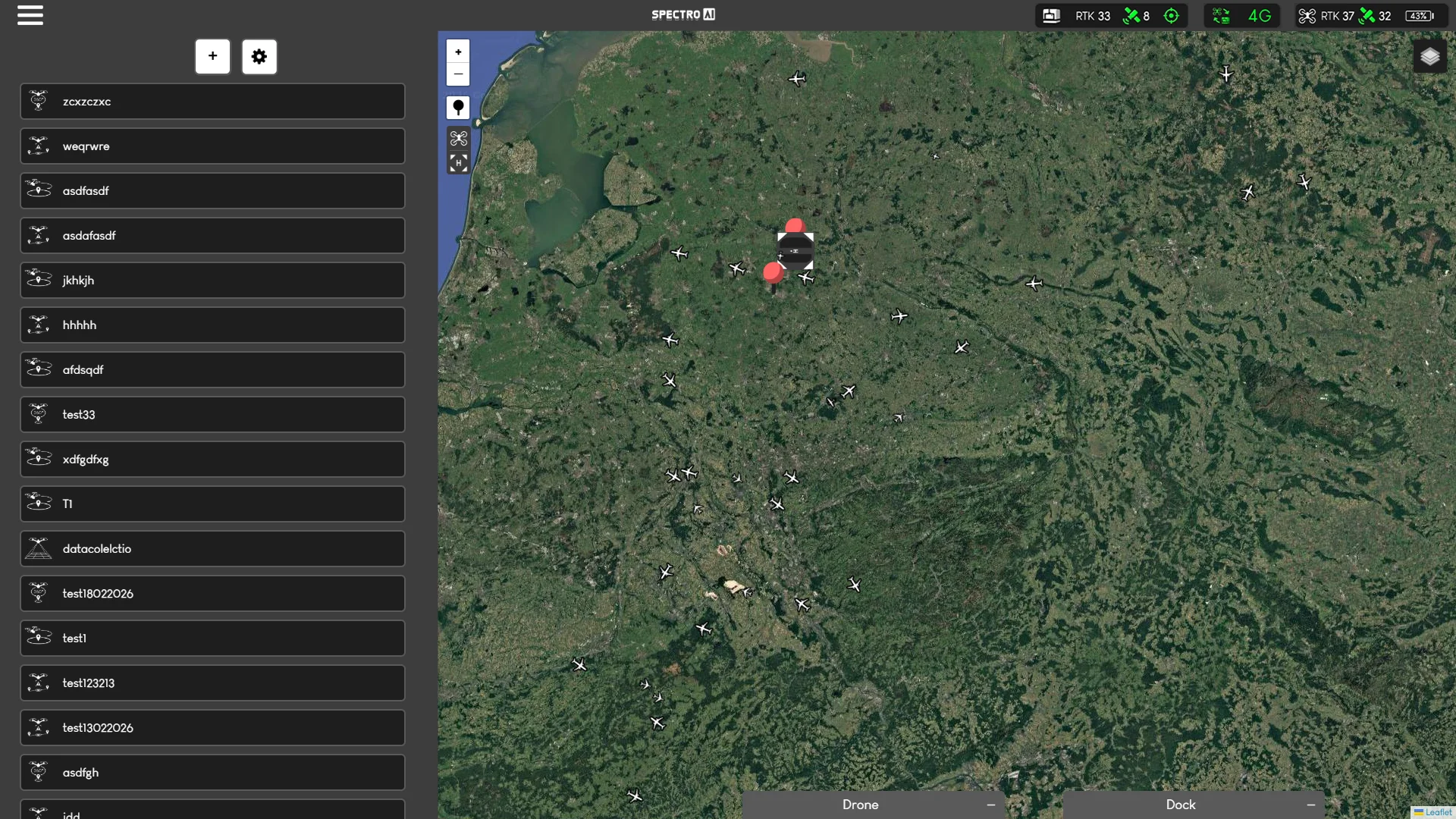
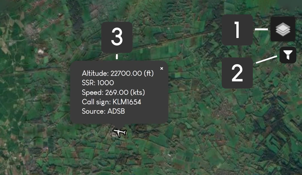
In this second air traffic example, the numbered markers highlight the main interactive parts of the feature. 1 is the quick toggle used to show or hide all aircraft overlays on the map. 2 is the altitude filter in feet, which helps reduce clutter by limiting which aircraft are displayed. 3 shows the flight information panel that appears after you left-click an aircraft icon, giving the operator a clearer readout of that aircraft’s details without leaving the map view.
The air traffic overlay is toggled on/off using the icon below the connection status bar in the top right. The overlay also includes a configurable altitude filter in feet, and left-clicking a plane icon on the map opens the flight information panel for that aircraft.
Air traffic monitoring is informational only. It does not replace mandatory regulatory compliance or formal airspace deconfliction. Always follow local aviation authority requirements for drone operations.
API Integration
API Integration enables custom connections between SAI-HUB DD and third-party systems, including cameras, environmental sensors, and other site equipment.
- CamerasConnect additional visual monitoring sources to a tailored workflow.
- SensorsBring data from environmental or operational sensors into a custom integration.
- Custom SystemsExchange data with other site software or hardware through a project-specific API connection.
Contact Spectro AI to discuss your equipment, data requirements, and the most suitable integration approach.